Electromagnetic FEA Simulations
We can create rudimentary 2D and 3D FEA simulations of current carrying wires and permanent magnets in free space using only two equations:
For current carrying wires we use Biot-Savart:
Current carrying wires get boundary conditions, and in this case a single value representing the _Idl _term. It is assumed that all wires are pointing directly into or out of the page, so the cross product Idl x r_hat' term will always use an angle of 90 deg. Also note that we are calculating magnetic field strength H and not flux density B, despite the equation above, so no u_0 term.
For permanent magnets we can use the equations for point source magnetic dipoles:
Magnetic dipoles get boundary conditions and a magnetization vector m, which can be applied to a magnetic region at any angle and magnitude within the XY plane. The dirac delta term is applied only if calculating magnetic field strength inside a magnetic material.
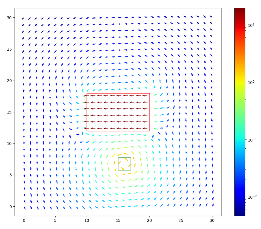
The rest is surprisingly simple and can be implemented in about 100 lines of code in Python. We can make a numpy array that computes the effect of any dipoles or current carrying wires on every location of a uniformly spaced grid of "elements." Each element is assigned a field strength in X and Y, and a material property such as air, magnet, or wire. By iterating across every field-producing element's effect on every other element, we can create vector fields representing magnetic field strength H like the one below, which shows a permanent magnet (red bounding box) with m pointing in -X, and a current carrying wire (green bounding box) with current flowing out of the page.
Examining the results above, there are some innacuracies and limitations worth noting for improvement:
-
First let's note that there appears to be divergence on the left and right bounds of the permanent magnet where the field changes direction. I initially assumed that this was incorrect, but it turns out H fields are indeed divergent at the boundary of a magnet, and Gauss's law for magnetism applies to magnetic flux density B, but not field strength H. This should really be apparent from the fact that H = B/u_0 - M, where the magnetization vector M is just a uniform vector field that sources from one side of the magnet and sinks into the other, as shown in the image linked to above.
-
The field strength inside the permanent magnet appears to be several orders of magnitude stronger than outside the magnet, and the field strength vectors are all extremely parallel (this is the result of that dirac delta term noted earlier). This is actually incorrect as noted by Erik, and the reason is that the magnetic dipole equation is not valid for calculating the field strength contribution of an element to itself (r must be significantly greater than the radius of the Bohr magneton or else the dipole equation suggests a field strength approaching infinity as we divide by r=0). With that said, the above simulation should be valid for field strength outside of permanent magnets
-
Solving for systems with ferritic or "magnetizable" materials requires iteration and annealing, and therefore this simulation tool is limited to materials with permeability of free space. A magnetized ferromagnetic material proceeds to produce an H field of its own, which in turn changes the H field generated on the first solve from any wires or permanent magnets. This process must then be iterated through until the solution converges to some acceptable degree.
-
Finally one additional thing worth addressing is that we have not yet seen a reason for commercial EM FEA modeling systems to require an infinite "air domain bound" to guarantee accuracy. This suggests that their underlying physics engine is doing something completely different, and it would be interesting to try and address that moving forward.
Attempt 2 - Magnets as Current Sheets
Lots of improvements to make after several very productive conversations and whiteboarding sessions with Erik…
Supplementary Materials
2D Simulations
Infinite Wire Approximation
Things get more complex when trying to extrapolate these 2D simulation results to 3 dimensions. For example, Biot-Savart tells us the contribution of the infinitesimal wire length dl, but what if the wire extends 5cm into the screen? In that case the sum of contributions from each element dl all contribute to the field strength at point A, but with increasing effective radii, and decreasing angle theta, which results in the cross product dl x r_hat also decreasing in magnitude. It turns out that if we integrate the contribution of an infinite wire on a single point A, we scale Bio-Savart by a factor of 2r. For small distances r relative to the length of the wire, this is a valid assumption, where true 3D FEA would likely be necessary for better resolution.
Coil Approximation
In the case of a coil, the distance r remains constant for an entire circumference of wire (assuming it isn't spiraling), and therefore we can scale Biot-Savart by
>>>>> gd2md-html alert: equation: use MathJax/LaTeX if your publishing platform supports it.
(Back to top)(Next alert)
>>>>>
. This is also true for points not at the center of the coil, as the sum of distance to the edge of a coil is constant*** not sure about this.
Motor Questions
This project attempt to answer some non-intuitive motor design questions through simulation, fundamental equations, and hopefully some homemade discrete 2D EM (static) FEA.
1) What are the tradeoffs of using larger rotor magnets which provides more H, but increases the reluctance due to magnetic material's low permeability?
- Model an "infinitely long" 5mm diameter cylinder magnet and show diminishing returns for flux at the front of the magnet.
- Then model a coil with a yoke opposing it and increase the distance of the yoke to show diminishing returns there.
- Then with these two plots it should be possible to find an optimal distance, assuming nothing saturates. Some blogs have suggested that an infinitely long magnet is ideal. There must be flux contributed from both the rotor and stator to produce torque, but what is the right balance between these two? The plot below shows increasing magnet thickness (x-axis) and diminishing returns in shear force.
This plot jumps right to the conclusion and shows shear force with increasing magnet thickness along the x-axis. Starting at about 2 mm, we begin to see very diminishing returns in terms of shear force vs. increasing magnet thickness. To be determined is the tradeoff between the PM's contribution and the relative increase from
2) Is there a penalty to having a large insulator (which creates a high reluctance gap) between your motor steel and winding? Is it optimal to ensure that your winding is wrapped tightly against the inductor?
- H field produced is defined as the product of amps flowing through a winding and number of turns in that winding.
- Having a larger diameter coil increases the resistance of the winding, so perhaps the tradeoff is that we are creating a lot of flux that doesn't get used or gets canceled because there are more windings in the way.
- If you have a small steel core at the center of a large diameter of windings are you being punished?
3) What is the effect of filling an air core winding to the core with windings? Diminishing returns? Higher peak flux at center but lower exterior? Would an optimal coil have the smallest possible wall thickness?
- This would be a good one for FEA generally, but there's difficulty in that the ID increasing must effectively mean fewer coils, so it's necessary to compensate for both.
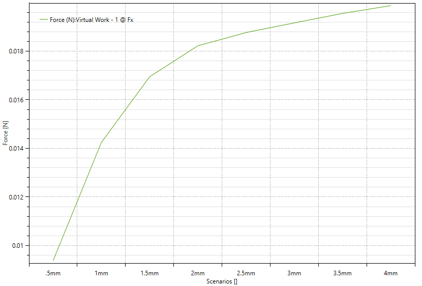
To start a simulation was run with constant amp-turns and increasing ID. Keep in mind that this was run with the optimal displacement as found in the sweep below for a 1mm ID at 2mm displacement. So it's possible that the magnet's location is convoluting this data a bit (more on that later). Interestingly there's a clear inflection point at 3.5mm corresponding to nearly double the shear force created in the .5mm case.
These results provide a strong basis for the possibility that tightly wound inner windings are contributing negatively, and so future sweeps here will need to be run manually to vary ID and have a % reduction in amp-turns corresponding with the coil area lost by increasing the coil's ID.
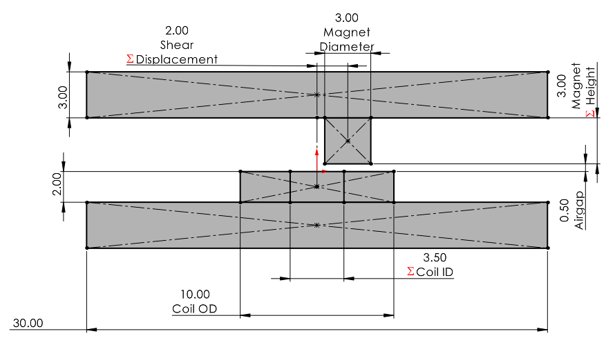
With that said, 3.5mm corresponds with the ID lying almost exactly on the center of the 3mm diameter of the magnet (see image below), so perhaps the takeaway is just that optimal shear will be produced at the point where the ID begins? To test this, lets re-run that offset code to make sure that the "Shear Displacement" parameter is still correctly set to 2mm with a now much larger ID.
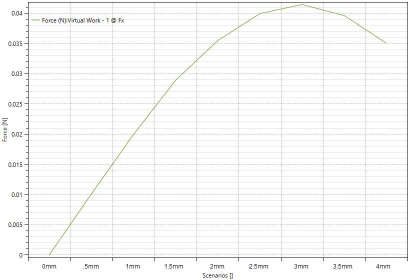
Again a sweep for optimal torque producing rotor displacement was run, analogous to load angle (max when 90 deg but unclear for this single pole linear displacement case). See CAD above for exact dimensions. Interestingly with this new ID, the optimal torque producing location has shifted up to 3.5mm. This suggests that iteration after tweaking certain parameters will be necessary to really converge on an optimal solution.


