Board Design
OK, normally I get really longwinded about this. Not today! I drew this board after a major revision of another version using the TMC262 and some small P-and-NFET H-Bridges, which were a cool part, but obsoleted for me now that I discovered the TMC2660. Really should have looked harder for that.
The business is done by a Trinamic TMC2660.


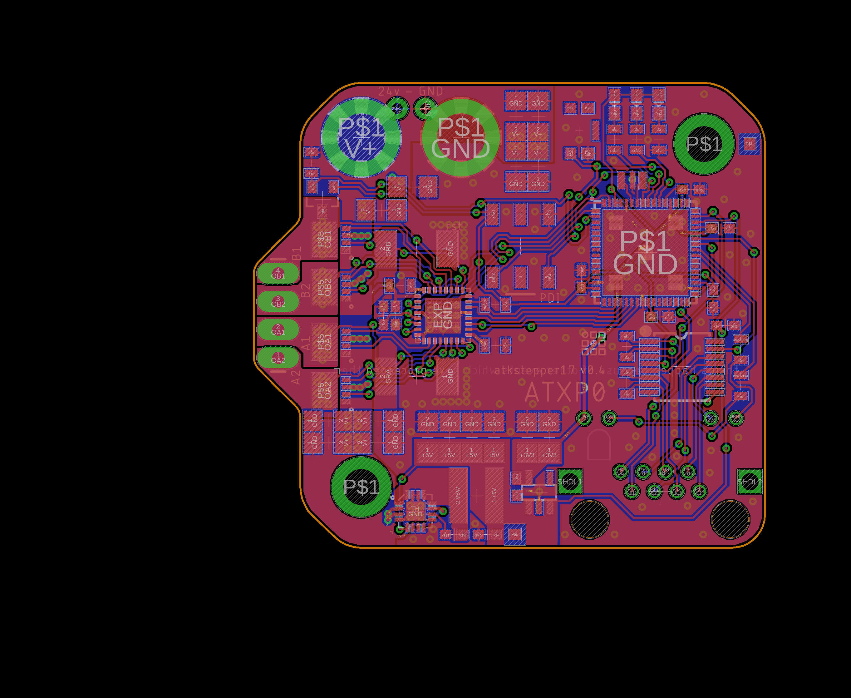
The TMC2660 is a bit odd in that it sinks heat out of the pins only (most motor drivers will have a big heat-dissipation pad on the bottom: see the DRV8302 in my bldcdriver). When I route the board, I use big polygons of infill for the motor drive lines (this is what the TMC datasheet suggests is the best way to pull heat from the board).
You'll also notice that I haven't done an excellent job of providing a solid ground plane! :|

Board Fab
I had this manufactured, and got the solder stencil, so that just left me to place components and reflow. Somewhere along the way I royally screwed up my reflow profile. Next time I fab a set, I'll put an image here, and start the programming folder.

Scope Traces!

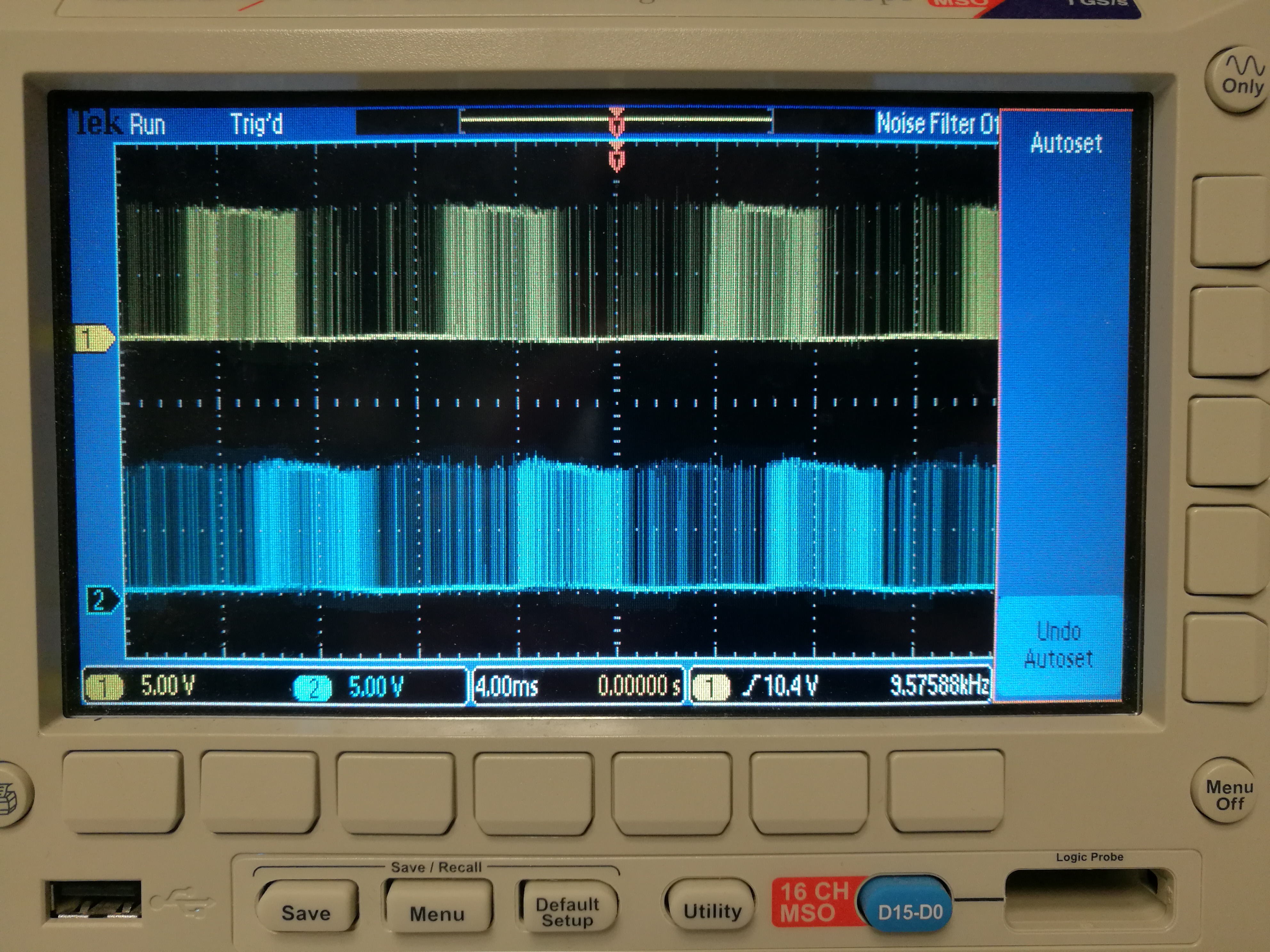
V0.3
Ok, I just blew one of these drivers up. Not sure what's up.
There's also a stray issue where the first apaport isn't working. the uartport runs messages out, but is maybe not catching any characters in, or something else, who knows.
I also notice that I see some current through the vcc pin apparently coming from the logic side, I should test to see if this is the case on the old drivers as well. I've compared schematics and I can't see any issues, so unless these came back from the fab with a trace error?
That's it - I had accidentally set two polygons to the same rank in eagle, connecting the +3V3 net to one of the motor outputs. Whoops! Fixed this by cutting the trace.
UP0 was on RX: {P29, PA12, SER4-1}, TX: {P30, PA13, SER4-0}