
Generating Dynamical Models of Extrudate Flow
Originally published to https://github.com/jakeread/generating-extrudate-flow-models in the wee hours of March 11th, 2025
I hereby dedicate the contents of this disclosure to the public domain so that it may serve as prior art.
3D Printers spend most of their time accelerating and deccelerating because their motion platforms are controlled by actuators with limited torque, and their structures and transmissions deflect during changes to velocity of the end effector. These physical limits, combined with limits to flowrate (and some other details) are the main limit 3D printing speed. Controlling flow under these dynamical conditions (stopping and starting) presents challenges to printer controllers (and parameter tuners) that can be overcome in a sensible way using models of the flow.
However, models are difficult to build because flow is difficult to measure directly, and instead we need to rely on indirect measurements - normally measuring track width in a test article where we have prior knowledge of motor speeds. In this disclosure, I show how I currently accomplish this (in a manner similar to many other pieces of prior art), and expand to explain a system I am currently implementing, which extends the prior art to enable us to capture flow data for arbitrary geometries - i.e. at each new layer or subsection of a print.
| With 100mm/sec Feedrate | With 500mm/sec Feedrate |
|---|---|
 |
 |
 |
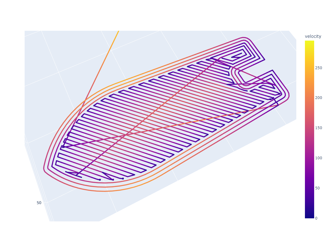 |
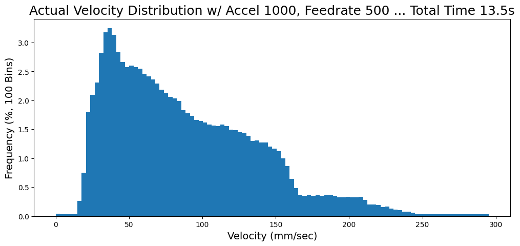
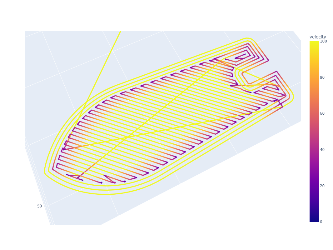
Here I show the result of two print layers that have been optimized by a trapezoidal motion solver (the likes of which are present in most machine control firmwares). In both cases, acceleration is limited to 1000mm/sec^2. At the left, we target 100mm/sec feedrate and the histogram shows that the resulting path is executed mostly at that feedrate. On the right, we target 500mm/sec, but see that this speed is never reached during the print: the job is acceleration dominated and instead of seeing a 5x increase in speed, we realize only 14% increase... the machine effectively spends 100% of its operating time accelerating, where flow dynamics become messy.
The most obvious type of dynamical information we need to understand is extrudate compression: when we apply a linear increase in pressure to the material we are depositing, it does not result in a linear increase in flow. Instead, the extrudate squishes somewhat, generating pressure, and then that pressure results in more flow. In most 3D printer firmwares, the compensation for this is known as linear advance and the required model is... linear!
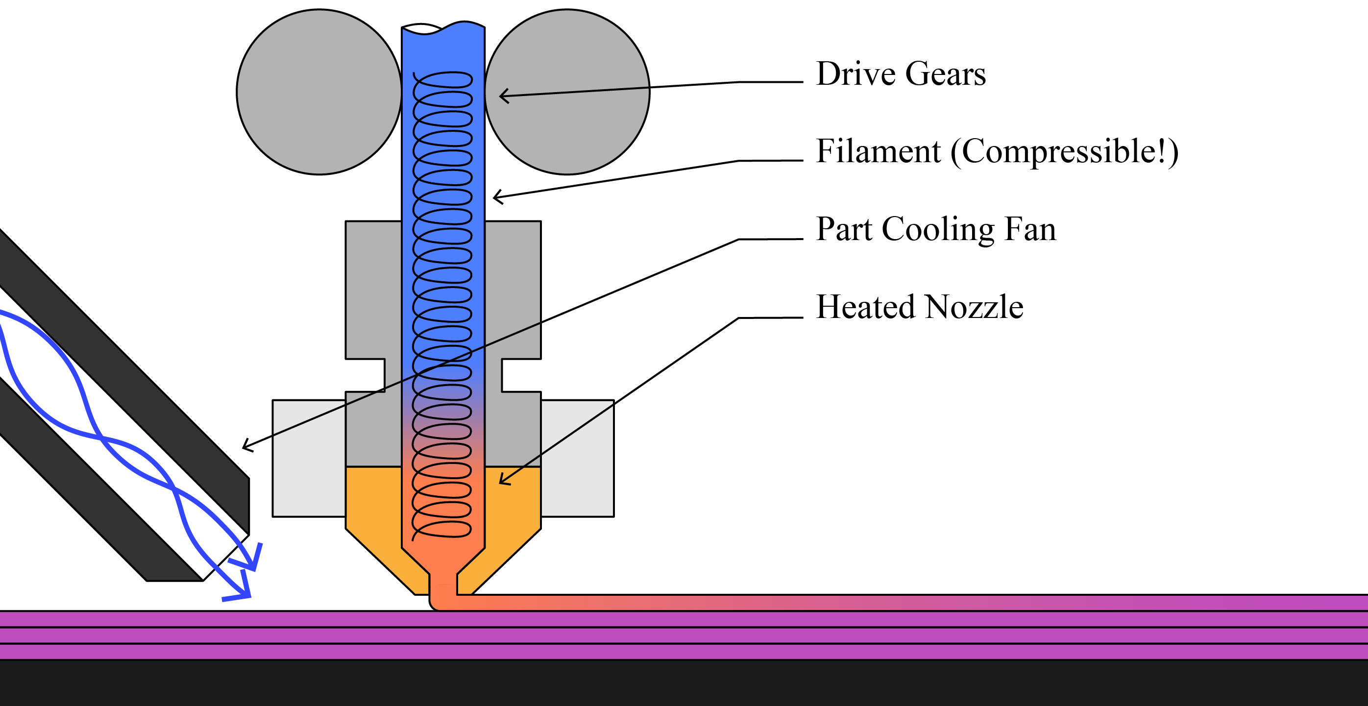
A diagram of an FFF printer's basic phenomena. Filament between the drive gear and nozzle is compressible, leading to some nasty extrusion dynamics. Extrusion is further complicated by nonlinear shear thinning of materials, die swell of extrudate processed at high pressures, and many more parameters. While this disclosure largely discusses FFF printing, the principles can be easily applied to pellet extruders, syringe extruders, pump extruders, etc - just about anything where a flow can be modelled and controlled.
Poorly understood filament dynamics can lead to extrusion errors when machines turn corners or slow down and speed up. A common heuristic remedy for this problem is known as 'linear advance,' but it is difficult to tune and misses nonlinear properties of extrudate flow dynamics. via the Prusa Knowledge Base
There is much more to it: flow is nonlinear with respect to pressure due to shear thinning properties of polymer melt flows (and many other types of extrudate). The temperature of a flow may change over time; even with constant nozzle set-points, the actual flow temperature fluctuates when the material spends more or less time in the heating element during slow or fast motion respectively. Capturing all of these phenomena in classic models is difficult, and so we and others are making efforts to develop data-based models.
If we had really good models of melt flow rheology and its relationship to polymer material properties across a range of temperatures and shear rates, it may be possible to build feed-forward flow models, but (1) those models are nasty and nonlinear, (2) there is lots of other hidden, unmeasured state (like exact flow pressures and shear rates) (and melt flow temperature, which as mentioned is not identical to nozzle setpoint temperature!) and (3) we often don't know exactly what polymers we are printing, since we buy them from many different vendors, etc etc - nozzle internal geometries may also be unknown, as would be the actual force exerted by our motors, etc. We need flow data!
Capturing Flow-Rate Data
The most straightforward way to get real flow data is to measure a track width in a situation where we already know the track's height and the forward velocity that our machine had while that track was made.
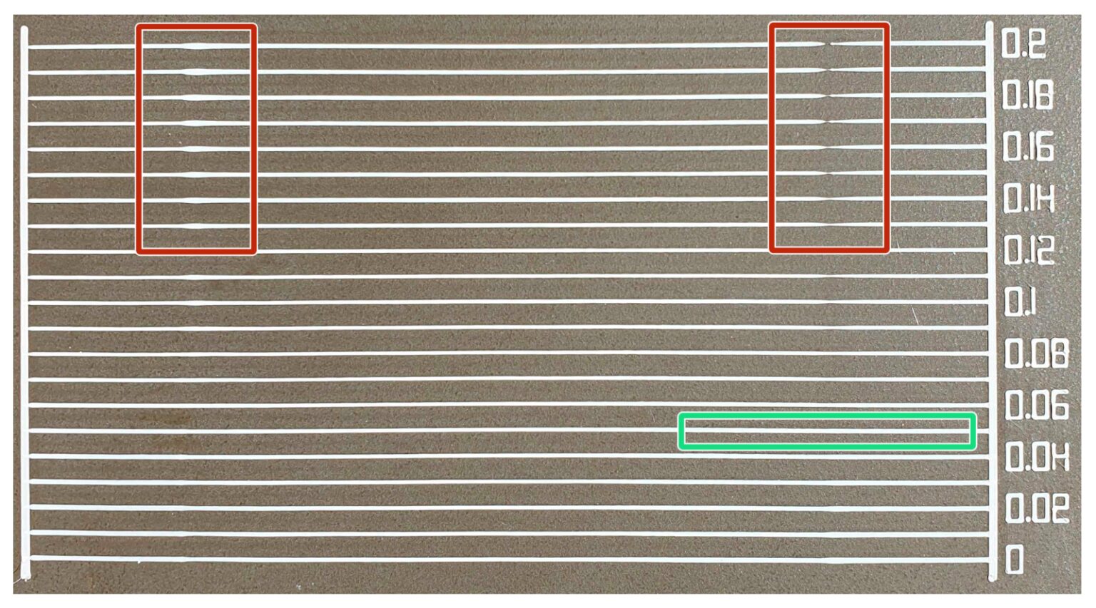
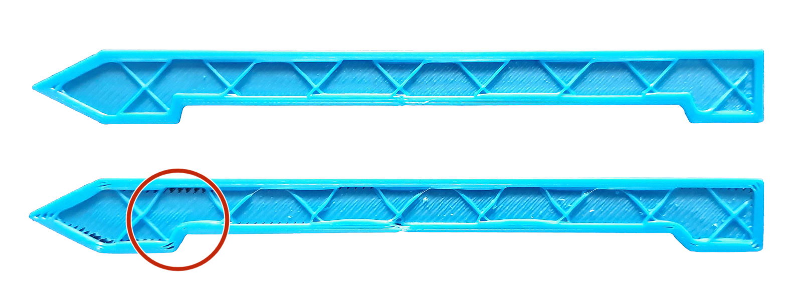
This is a test article for manual calibration of linear advance via the Prusa Knowledge Base - at each line, the linear advance value is updated (and printed at right). In this procedure, the test article is printed and then users select the value which produced the most even line.
This is basically what the Bambu printers appear to do, and similarely documented in rubedo: a system for automatically calibrating pressure advance using laser triangulation as well as in this excellent thesis by Pinyi Wu. It is also similar to what I have done previously with contributions from Yuval Manana at MIT.
 |
 |
|---|
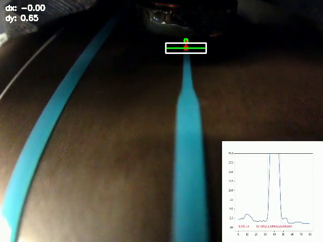
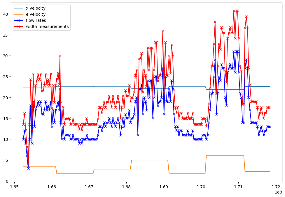
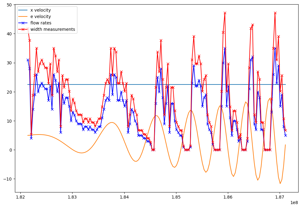
In the video above, I show how camera data can be used to capture line widths, which are then converted from pixels widths to flow values (using prior knowledge of the machine's velocity). These can then be correlated with the machine's extruder motor velocities at the frame capture times in one time-series dataset.
Quality of the imaging data can be improved by adding a line laser, as is the case in most other implementations. These implementations themselves are essentially laser profilometers, a very well understood device figured below.

An off-the-shelf laser profilometer from Micro-Epsilon. These devices project a line laser, and use an imaging device to measure the laser's position on an image plane. A few transforms later and this is turned into height data - which can be used for edge detection, volume calculations, etc.
In the state of the art, this is done on the first layer in a mostly offline calibration routine: a canned pattern is printed, and scanners recover flow data from that pattern. However, these canned patterns cannot capture the full breadth of dynamical information that is useful in building and refining flow models. A primary limit here is that the first layer of a print is normally much slower than subsequent layers (since bed adhesion is troublesome). A second limit is that canned patterns contain smaller breadth of different dynamical states - of course, complete 3D prints are more representative of the dynamical states that a machine will typically find itself in!
What This Disclosure Contributes
I have devised a procedure / system that would let us gather width (flow) information from any layer in a print. The sysem would allow our printers to learn (1) with more and higher frequency data and (2) on real in-situ data from the printers' active settings (not only on a canned routine).
This strategy would also allow us to improve measurements on the fly (3) in cases where feedstock or other processing conditions may change. Additionally (4) it would enable the printer to stop, modify, or save data about ongoing prints for future use in industrial verification, part traceability, and collect detailed measurements of any print it carries out to study longer-order outcomes like part strength, layer strength and durability, by effectively scanning internal layers as they are printed.
While the implementation discussed herein is for an FFF 3D printer, the techniques could be broadly applied in pellet 3D printers, gel, clay and concrete extrusion, etc.